
Learn how to calculate the required thickness and plan dimensions of a steel base plate, according to Eurocode 3.
Introduction
Steel base plates are provided beneath steel columns in order to transmit the applied design forces safely to the foundations. Since steel columns are heavily loaded and their cross-sections are typically small, applying the loads directly on the foundation could result in a punching failure. Therefore a base plate must be provided beneath the column in order to spread the column load over a larger base area.
.png)
Design approach according to Eurocode 3
The actual distribution of pressure beneath a base plate is quite complex. EN 1993-1-8:2005 clause 6.2.5 and 6.2.8 presents a simplified approach. It assumes a uniform distribution of pressure beneath an effective area of the base plate known as the "equivalent T-stub in compression". The dimension,
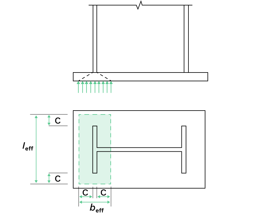
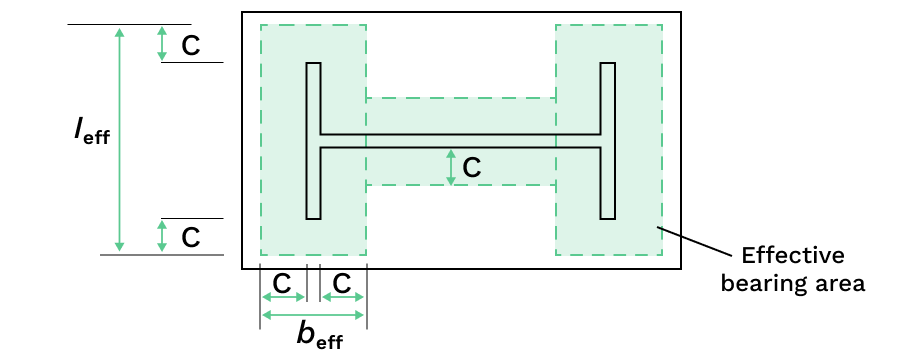
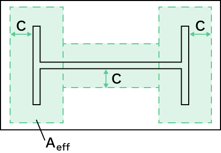
As per Clause 6.2.8.2, the capacity of a symmetric column base plate subject to an axial compressive force applied concentrically may be determined by adding together the capacities of the three T-stubs shown below (two T-stubs under the column flanges and one T-stub under the column web). The three T-stubs should not be overlapping.
The required check is that the applied compressive stress on this effective area does not exceed the design bearing strength of the concrete support,
Step by step design guide
Let's walk through the steps for the "equivalent T-stub in compression" design method, which are based on a research paper from the University of Ahmadu Bello. It checks the bearing strength of the concrete support and determines the required width, length and thickness of your base plate.
Step 1: Compute the bearing strength of the concrete support,
Where:
: the foundation joint material coefficient, typically taken as 0.67 as per clause 6.2.5(7) in EN 1993-1-8. : coefficient which accounts for the concrete bearing strength enhancement due the diffusion of the concentrated force within the foundation, as per clause 6.7 in BS EN 1992-1-1 (code also known as "EC2"). The value of can be calculated directly if the dimensions of the concrete foundation is known. Otherwise, usual foundation sizes relative to that of the baseplate is shown to give (source: SCIA Engineer). : characteristic compressive strength of the concrete support : concrete coefficient for long-term effects, refer to your country's National Annex. : partial factor of safety for concrete, refer to your country's National Annex.
The equation for
As per clause 6.2.5(7) in EN 1993-1-8:
As per clause 6.7 in BS EN 1992-1-1:
As per clause 3.1.6 in BS EN 1992-1-1:
Putting these three equations together gives our final equation:
Step 2: Find the required area of the base plate,
Where:
: ULS design compression load from the column on the baseplate : bearing strength of the concrete support
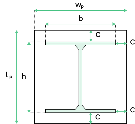
Step 3: Find the additional bearing width,
The additional bearing width,
Step 4: Find the required base plate plan dimensions
Required baseplate width,
Note, as per EN 1993-1-8:2005 Section 6.2.5(5)&(6), if the baseplate has larger plan dimensions then required to fit
Step 5: Calculate the required base plate thickness,
Re-arranging the equation in clause 6.2.5(4) EN 1993-1-8 gives the required baseplate thickness:
Where:
: yield strength of the T-stub (i.e. the steel baseplate) : bearing strength of the concrete support : partial factor for resistance of cross-sections whatever the class is as per EN 1993-1-1, where the code recommended value is